Cable Test Van Baur Professional
Price on request
check_circle_outline Get pricePrice on request
help_outline Get priceHigh-voltage cable electric laboratory Baur Professional
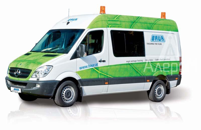
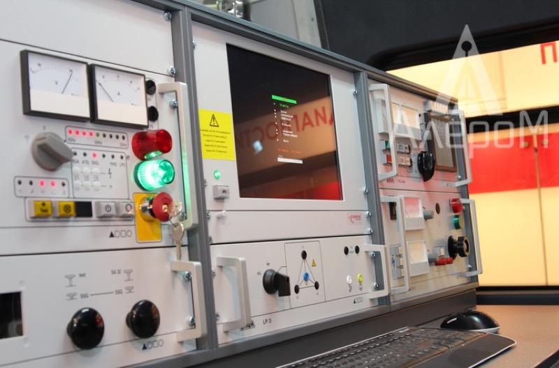
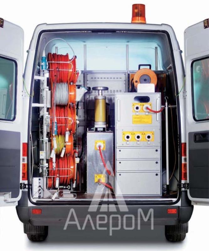
The mobile electric laboratory produced by the top-ranked European manufacturer BAUR is designed for diagnostics and faultfinding, as well as for testing cable lines. The electric laboratory Baur Professional is equipped with modern equipment and provides operators with all the necessary working conditions.
At the customer’s discretion, the mobile high-voltage electric laboratory can be produced on the basis of foreign chassis, including Ford, Volkswagen, Mercedes, as well as the ones produced by Russian manufacturers.
| № | Name | Specifications |
| Mercedes Benz Sprinter | Specifications:
– engine: diesel 215 CDI – engine power: 150 hp – drive: rear Van: – interior lighting 220 V AC and 12 V DC; – finishing of the interior with thermal insulating material and plastic panels; – manufacturing of antistatic floor in the operator compartment; – manufacturing of the floor made of special aluminum tread plates in the high-voltage compartment; – installation of a protective transparent partition between the operator compartment and the high-voltage compartment, working table and swivel chair; – cases for storing accessories; – industrial computer; – multifunctional device (copying+printing); – special identification marks and inscriptions in accordance with the customer’s standards. |
|
| Corollary equipment | – Auxiliary interior heater Webasto 2.0 kW;
– Petrol generator 6 kVA; – Roof conditioner. |
|
| Electrical equipment | ||
| MGS 32 | Control unit for all processes | |
| Accessories for synchronization: | ||
| CC 1
|
Communication system for measurement using the voltage oscillation method | |
| SK-1D
|
Communication system for measurement using the current oscillation method | |
| DESK C
|
Desk for installing units mounted in a 19-inch equipment rack, with a steel frame covered with epoxy resin. The top of the desk is angled 3° from the vertical | |
| Safety system | ||
| Automatic grounding control system for providing correct grounding mode of the laboratory with monitoring of the grounding of the high-voltage cable shield and the protection grounding cable. | ||
| Automatic auxiliary grounding system for monitoring the difference of potentials between the earthing ring of the station and the earthing of the vehicle. | ||
| EAM 70
|
Automatic system for high-voltage release from the test unit and equipment | |
| Blocking system and laboratory emergency tripping device. | ||
| Sound-and-light alarm system. | ||
| Set of personnel protection equipment against electric shock. | ||
| Insulating transformer 5 kVA. | ||
| Door electric contacts. | ||
| Signal lamps (set of lights) | ||
| IRG 3000
|
IRG 3000 reflectometer
Field of application IRG 3000 reflectometer is designed for preliminary faultfinding in all types of cable lines. The operating principle of the reflectometer consists in analyzing the signals reflected from the inhomogeneities in the cable line. To ensure high accuracy of measurements, IRG reflectometers have a built-in transrecorder with a scanning frequency of 200 MHz. Distinctive characteristics of the device are as follows: a user-friendly interface with a simple menu, the possibility of fully automated measurement, scaling of measured parameters and automatic selection of the cursor position. IRG 3000 reflectometer can also be used in networks with the voltage up to 400 V for specifying the condition of the cable without the voltage release from the cable. When used as part of mobile laboratories and integrated faultfinding systems, such as Syscompact, it enables the implementation of the most advanced methods for detecting high-resistance defects and floating breakdowns, such as the secondary impulse method (SIM).
Features: • User-friendly interface with a simple menu • Possibility of fully automated measurement • Auto-scaling of measured parameters and automatic selection of the cursor position • Enables maintaining of a database with information on cable networks of the enterprise
IRG 3000 • When used with a high-voltage pulse generator and a high-voltage test system, it implements the whole range of preliminary faultfinding methods
Measurement methods: – Reflectometric method – Secondary impulse method (SIM) – Secondary impulse method with additional arc stabilization (SIM DC) – Multiplexed impulse method (MIM) advanced SIM – Differential secondary impulse method – Impulse current method (ICM) – Voltage wave reflection method
Specifications: Output voltage of impulses 20…160 V Duration of the probe pulse 20 ns – 1.3 μs Electrical strength to the input voltage 400 V AC (50-60 Hz) Output impedance 12-2000 Ohm adjustable Sensitivity of the input divider -10 dB…+60 dB Measurement range (at v/2=80 m/μs) 0 – 1000 km Signal pickup increment 200 MHz (5 ns) Resolution 0.1 m (at i v/2=80 m/μs) Accuracy 0.1% Rate of propagation v/2 20-50m/μs Memory capacity of traces> 100 000 Display TFT 15 Supply voltage (work and recharge of the battery) 100-240 V (50/60 Hz) Battery operating time – about 5 hours Operating temperature -20…+50 °C Storage temperature -40…+60 °C Protection according to IP54 Dimensions 483 mm x 365 mm x 174 mm Weight 12 kg |
|
| ATG 6000
|
ATG 6000 burn-down transformer
Field of application ATG 6000 is a testing device that uses the insulation burn-down method. It is a device for faultfinding in cables. It is used to convert high-resistance cable faults into low-resistance cable faults by “burning-down” in a constant arc discharge. Using devices for faultfinding in cables, low-resistance defects can be detected more easily than high-resistance defects. Due to the possibility of incremental change of the maximum output voltage, there is the possibility of individual adaptation of ATG 6000 to the specific situation of faultfinding. It is possible to increase the current by stepwise decreasing the output voltage during the burn-down operation after the “breakdown” at the location of fault. ATG 6000 is equipped with an automatic discharge device and is able to ground the test object. In addition, ATG 6000 has an external ohmmeter. It can measure the resistance at the fault site.
Features: – Output voltage up to 15 kV DC, 6 kVA – Maximum output current 90 A – Availability of 8 ranges of output voltage; range switching even with full load – Protective circuit in accordance with VDE 0104 – Individual electronic regulation of current and voltage – Operation at full output power for a maximum of one hour |
|
| SSG 3750
|
Pulse voltage generators SSG 3750
Pulse voltage generators provide an accurate location of high-resistance and low-resistance, as well as intermittent errors in high, medium and low voltage cables. The output voltage is smoothly regulated in the range of 0-8 kV, 0-16 kV and 0-32 kV. High-power capacitors are discharged into the damaged cable cyclically or by means of a pulse switch with electromagnetic control. When disconnected, the connected high voltage cables and internal pulse capacitors are discharged automatically and separately from each other.
Characteristics: ● High impulse voltage up to 32 kV ● Voltage is smoothly adjustable ● Voltage monitoring by means of a kilovoltmeter with 3 measuring ranges ● High pulse energy ● Automatic discharge device SSG 3750 ● Pulse switch with electromagnetic control and heat resistant tungsten semi-spheres ● Safe operation according to VDE 0104 ● Transition joint for external emergency tripping with indicator lights ● 4 optional operation programs: – Single pulse – Low pulse frequency – High pulse frequency – DC output ● Thermal overload protection ● Control output for SA 32 (SIM-MIM) connection system Specifications: Pulse energy 3750 J Electric line voltage 220-230 V Network frequency 45 Hz to 60 Hz Max. power consumption 5.000 VA (with short circuit) Max. output voltage 32 kV Output voltage ranges 0-8 kV 0-16 kV 0-32 kV Max. pulse energy 2048 W Pulse frequency 10, 20 pulses/min Max. output current in DC mode Voltage range 0-8 kV 850 mA Voltage range 0-16 kV 425 mA Voltage range 0 – 32 kV 210 mA Accuracy of the kilovoltmeter is 1.5% |
|
| TG 600
|
Audio frequency oscillator TG 600
Description TG 600 generator is designed for both mobile laboratory equipment and autonomous use with mains power and 600W output power. Together with the receiver of audio signals UL 30 and detector coil SP 30, TG 20/50 generator is used for route tracing, estimating the depth of the cables and faultfinding using the induction method.
Features: • Output power 600W • Automatic or manual impedance matching • Ability to choose work in continuous or pulsed mode • Ability to select one of two output frequencies • Output impedance 8-step adjustment from 0.3 to 300 Ohm • Thermal overload protection • Adjustable reactive power compensation • High output power, so it is possible to apply the torsional wave method • Indication of the output current Iout and the input current Iin.
Specifications: From mains 220-230 V Frequency of the mains voltage 50-60 Hz Output current 30 A Output power 600 VA/60 VA at 2 kHz 450 VA/45 VA at 10 kHz Output impedance 8-step adjustment 0.3/0.8/1.8/4/10/30/100/300 Ohms Frequencies With quartz stabilization: 2 kHz and 10 kHz; Other frequencies – on request Operating modes DC voltage mode and pulse mode Display of 2 dial gauges for indicating the input and output currents Compensation of the reagent is regulated (63 steps) Power consumption 1800 VA with an output power of 600 VA Overload protection Overheat tripping Overheat indication |
|
| SA 32
|
SA 32
Communication unit for the pulsed voltage generator This unit provides the ability to localize the defect in accordance with the SIM method and with the improved SIM/MIM method when using IRG 3000 with a pulsed voltage generator. SA 32 together with the pulse voltage generator is used as an additional source of high voltage DC with voltage up to 32 kV for testing the cable for breakdown at max. current up to 200 mA. Using the switch, it is possible to switch between impulse mode and test mode by increased DC voltage. The principle of the Secondary Impulse Method (SIM): The pulses that are sent by the reflectometer to the cable will not result in a visible reflection on the shield from the fault location in the case of a floating high-resistance defect in the cable. Only the reflection of the positive polarity from the far end of the cable will be detected. At the second stage, the electric arc is “ignited” at the location of the insulation fault by a single high-voltage pulse from SSG 2100 (or from a direct current source from PHG/PGK). Right at the time of the arc occurrence, a second measuring pulse will be sent to the cable from IRG 3000 dynamic reflectometer, which will be reflected from the arc and have a negative polarity, since the arc has a low resistance. Simultaneous reproduction of two waveforms enables to achieve the maximum accuracy of estimating the distance to the defect. The principle of Multiple Impulse Method (MIM): a dynamic reflectometer using a 200 MHz transrecorder can record 5 measurements, indicating the position of the defect, using only one high-voltage pulse! Program processing of the results of these five measurements using statistical analysis enables to obtain amazing results in reliability and accuracy (This is an improve secondary impulse method!) |
|
| Frida
|
High-voltage testing unit Frida
Portable and powerful testing unit Frida
Field of application ● Field test of medium voltage cables acc. to – VDE DIN 0276-620/621 (CENELEC HD 620/621) – IEEE P 400.2-2004 – IEEE 400-2001 ● Testing cable jacket/localizing cable sheath damage ● Testing insulation of electric devices, for example, rotating machines (engines and generators) acc. to IEEE 433 ● It operates in the burn-down mode for voltage up to 34 kV
Specifications – High voltage source VLF truesinus® – Fully automatic, programmable test mode – Transmission and storage of data using the infrared interface – Integrated automatic discharge device – Expandable to the diagnostic system of transmitter-distributor and terminal equipment
Specification: – Output voltage VLF truesinus® 1… 24 kV (1.4…34 kV peak) Constant voltage +/- 1…34kV Voltage of rectangular shape 1…34 kV Accuracy 1% Resolution 0.1 kV Output current Range 0…14 mA Accuracy 1% Resolution 100 μA Frequency range 0.01 Hz…0.1 Hz Input voltage 100…260 V, 50/60 Hz max. input voltage 1400 VA Operating temperature -10…+55 °C Storage temperature -20…+ 60 °C Protection class IP 44. protected from splashes of water and dust |
|
| Portable measuring instruments | ||
| Locator Set
|
Radiofrequency localization system Locator Set
Locator Set locating system is used mainly to accurately locate faults and locate underground cables and trace metal gas and water pipes. With a wide range of optional accessories, Locator Set becomes a universal and indispensable system for the maintenance of electrical networks, industrial and municipal water supply systems. The Locator Set system is used to solve the following tasks: – exact faultfinding in cables using the acoustic method; – exact faultfinding in cables using the so-called twist method, which is realized with the help of a powerful radio-frequency generator TG 20/50; – measurement of sound propagation time between the moment of magnetic pulse input and the moment of occurrence of breakdown noise for accurate faultfinding in cables, for example, cables located in pipes (universal locator UL 20). – tracing of cables and metal gas and water pipes; – evaluation of the depth of cables and metal pipes location; – identification of cables; – detection of live cables; – location of cables and their connection points.
Completeness of delivery – Universal receiver UL 30 – Audio frequency generator TG 20/50, power 20/50W – Surface microphone (acoustic sensor) BM 30 – Search coil SP 30 – Induction clamps for contactless signal transmission to the cable line AZ 10/D100 – Selective coil AS 10/20 – Headphones KH – Accessories Basic principles of operation of the set: the universal receiver UL 30 is used in conjunction with the surface microphone BM 30 installed on the surface of the ground and the high voltage generator SSG 2100 to find the fault location in the cable line. With the means for measuring the propagation time of an acoustic signal built into the BM 30, the difference between the arrival times of the electromagnetic pulse and the reception of the acoustic breakdown signal can be measured and evaluated. On this basis, the UL 30 reproduces the distance to the defect and indicates whether you have reached the defect site or are moving away from it. This is particularly useful for defects in cables where acoustic localization is difficult. In combination with the audio signal transmitter (TG 20/50) and the coil (SP 30), the UL 30 locator is used for tracing routes and estimating the depth of the cable lines. In accordance with the method of forming a step voltage, localization of defects in the envelope can be made using the two probes buried in the ground in the package. |
|
| SHIRLA
|
Cable sheath testing system and Shirla fault location
The faultfinding system is used for testing cables and cable sheath, preliminary faultfinding, as well as for cable sheath faultfinding according to Murray and Glazer. Using an integrated DC power source, shirla allows preliminary faultfinding in cables of low and even high resistance. The principle of measurement makes it possible to perform preliminary faultfinding, especially on unshielded control and lighting cables, as well as on the cable jacket. The analysis is performed automatically, and the results are displayed in digital form. You can consider different cable sectors. The preset pulse mode of direct current enables to carry out point in accordance with a step voltage method. ▪ Testing of cables and cable sheath up to 10 kV ▪ Preliminary faultfinding in cables and cable sheath (measuring bridge) ▪ Faultfinding in cable sheath up to 10kV in combination with selected KMF1 or UL settings ▪ Easy operation, menu control Powered by a battery with fast charging, as well as working with power from the network |
|
| UIV 100/70
|
Portable high-voltage testing unit UIV100/70
Purpose Portable unit UIV-100 is designed for testing insulation of electrical equipment with high voltage from 10 kV to 35 kV of industrial frequency of 50 Hz. Parameters and values Rated voltage, kV 100 Rated supply voltage, V 220 Rated frequency, Hz 50 The main range of generated voltages, kV 10-105 Additional range of generated voltages, kV *1-10 Test voltage of frequency 50 Hz, kV 110 Steady current of short circuit, A, not less than 1.2 Minimum load capacity, nF 0.0 Maximum load capacity at rated voltage, nF 1.9 (5.5) Maximum capacitance when testing block and control circuits, nF 15 Test power, kVA: – continuous mode 4.1 (-) – repeated – short-time operation, DC 10% 7.8 (18.5) Rated direct current voltage, kV 70 Ripple factor (no load), %, no more than 2 Maximum load current, mA 10 Maximum load capacity, μF 2 Maximum power consumption, not more than, kVA 4.4 Accuracy of high voltage measurement, % 3 Stability of voltage reproduction in the range, % 1 PD intensity with rated voltage, PCL, not more than 5.0 Weight of the complete set (net/gross), kg 85/110 |
|
| SDMO 9kVA
|
Diesel generator SDMO 9 kVA | |
| Cable drums | ||
| KTG | Cable drums unit | |
| NK | 50 m network cable, 3×4 mm2 | |
| EK
|
50 m grounding cable, 16 mm2 (current clamps every 3 m) | |
| HE | 25 m auxiliary ground cable, 2.5 mm2 | |
| KTG M 6-80 | Cable drum unit with cable | |
| НК 10/6 – 80 | 50 m high-voltage cable 80 kV | |
| Documentation | ||
| Set of documents | – Operations manual in Russian;
– Certificate of primary calibration of measuring devices that form an integral part of the laboratory; – Technical documentation for the car; – Electric schematic diagrams of ETL and fixed instruments. – Passports and methods of calibration of ETL and devices. – Methods of measuring and testing using ETL devices. |
|
| Warranty and service | ||
| Availability of own service department and production facilities | Arranging a workshop
The main goal of the workshop is to teach users how to operate the laboratory equipment properly. In the process of training, the customer’s specialists learn about the theoretical background of conducting high-voltage tests of power cable lines and methods of finding the damaged spots in them using equipment, as well as gain practical experience in working with the laboratory equipment. In case of large-scale supplies, the workshop is carried out at the enterprise of the laboratory user. – support service is carried out at the service center in Moscow; – warranty – 12 months; – post warranty service for the entire service life; – ability to upgrade the laboratory in operation. |
The high-voltage laboratory performs the following functions:
- High-voltage testing of power cables up to 10 kV with an alternating voltage of 34 kV of an extremely low frequency of 0.1-0.02 Hz;
- Testing of the insulation of electrical facilities with high voltage from 10 kV to 35 kV of an industrial frequency of 50 Hz;
- Burn-down of the damaged power cable insulation;
- CLP (cross-linked polyethylene) jacket tests;
- Faultfinding in high-voltage cables using the pulse-echo method and the arc reflection method;
- Secondary Impulse Method (SIM);
- Faultfinding in high-voltage cables using the acoustic and inductive method;
- Selection of a cable from the cable bundle;
- Faultfinding in the cable sheath.
| № | Technical solutions | Operational advantages of the cable laboratory |
| 1. | Burn-down transformer ATG 6000 | Maximum output current is 90 A |
| 2. | SSG 3750 | Maximum output voltage is 32 kV Pulse energy is 3750 J |
| Audio frequency oscillator TG 600 | Output capacity is 600 W | |
| 3. | Re-equipment of the base car and assembling of the laboratory |
Our experience and production base of “ALEROM” LLC enables us to manufacture laboratories of high quality, under the best conditions


