Cable Test Van ETL-35K
Price on request
check_circle_outline Get pricePrice on request
help_outline Get priceOur experience and production base of “ALEROM” LLC enables us to manufacture laboratories of high quality, under the best conditions.
| № | Name | Specifications |
| GAZ 33081 4×4 | Specifications
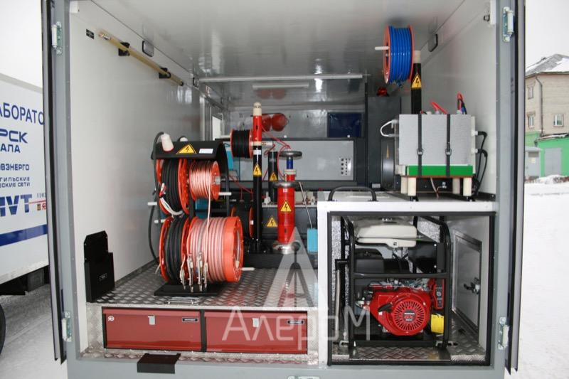
– engine: diesel; – axle arrangement: 4X4; – engine power: 117.2 hp; – overall length: 6750 mm; – dimensions of the van: 3700/2300/2000 mm (L/W/H). Features of the van: – type of the van – made of sandwich panels; – shape of the van – rectangular; – outer skin – white clad metal, 0.6 mm thick; – external and internal surfacing elements – aluminum angle; – upholstery – white glass-reinforced plastic supported on a 4 mm plywood; – insulation – extruded polystyrene foam 80 mm; – side one-piece door on the right side (handrail, ladder, deadlock locked with a key, hold-open latch); – rear one-piece door on the rear wall (handrail, ladder, deadlock locked with a key, hold-open latch). Windows (double-glazed windows) – 3 windows that can be opened: – in the living compartment – 1 on the right side, 1 on the left side; – in the working compartment – 1 with a curtain on the left side; – interior lighting 220 V AC and 12 V DC; – installation of a protective transparent partition between the operator compartment and the high-voltage compartment, working table and swivel chair; – boxes for storage of accessories; – industrial computer; – multifunctional device (copying + printing); – special identification marks and inscriptions in accordance with the norms of the customer. |
|
| Corollary equipment | – Auxiliary interior heater Webasto 2.0 kW;
– Petrol generator 6 kVA; – Roof conditioner. |
|
| Control unit | ||
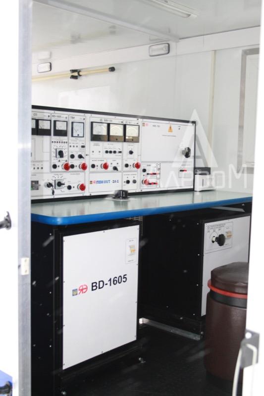
| Rack | Support construction, designed for laboratory equipment placing, table top. | |
| Network unit | Designed for switching of units and blocks of the laboratory through supply circuits, as well as for lighting and heating control of the laboratory cabin. | |
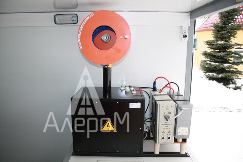
| Control unit | Control of high-voltage tests with measuring of the test voltage on the high side using the high-voltage measuring system HVS-100, which has the certificate of approval of the measuring instrument type (measurement error £ 3%);
Performance module NDE; Power distribution module; CU frame with panelling. It performs switching of high-voltage leads TIM 6 100/70, as well as UP-7-05, GVI 32/30, inductive generator, reflection-coefficient meter and megohmmeter to a high-voltage shield cable. |
|
| Voltage regulator | Designed for smooth regulation of the feeding voltage level. If the regulator is not in the zero position, testing is impossible. | |
| High-voltage testing unit | ||
| Test voltage source
TOT 6 100/70 (analogue of IOG 100/70) |
Maximum alternating test voltage is 100 kV. Maximum rectified test voltage is 70 kV; | |
| Mobile unit VLF-6022 CMF for high-voltage tests at the extremely low frequency of 0.1 Hz | This model, which has a peak output voltage of 60 kV, is designed for testing cables up to 35 kV. Its ability to operate into load with a large capacity enables to test up to about 16 km of cable based on the type.
The unit has an extended set of capabilities, including: a charging rate and loading capacitance meter, kilovoltmeter of the output voltage, timer for setting the test time and indicators of the output voltage polarity. The complete set of the laboratory as regards VLF-6022 also separately includes: Service Manual, Program and Methodology of Scheduled Qualification and Preliminary Test Record. |
|
| AUTOMATIC DATA RECORDER ADL-1
|
The automatic data recording and output device ADL-1 enables to track and record all test data, as well as transfer data to the computer wirelessly. This is the best combination to work with VLF unit: easy control of VLF unit and the availability of a complete set of data – wireless and local connection with a computer. It’s possible to view, record and store results on the computer, as well as print records and output data of ADL-1. This device is compatible with Windows. VLF units working together with ADL-1 are connected with one interface cable. ADL-1 is equipped with a wireless communicator and has the access to the Internet. The built-in memory provides recording of test results within 40 hours of operation. | |
| XDP-2 partial discharge detector (the analogue of OWTS, PD-SGS system)
|
Partial discharge test is a modern method for diagnosing high-voltage equipment.
– Diagnostics of partial discharges is carried out at the voltage equal to or slightly higher than the operation voltage, which virtually eliminates the negative effect on insulation; – Measurement of partial discharges can be carried out online, i.e. with the facility working, which makes it possible to control partial discharges in different operating modes; – Ability to localize problematic devices, sections of cable lines, spots with an increased level of partial discharges. Specifications |
|
| Faultfinding unit | ||
| Burn-down block UP-7-05 | Main electrical parameters of the burn-down module UP-7-05:
Output voltage taps Uхх, kV I short-circuit, А 1 ~ 0.160 23.6 2 ~ 0.450 8 3 ~ 1.400 2.8 4 -5.5 0.8 5 -11 0.4 6 -22 0.2 Power consumption – 4.4 kVA. Time of continuous operation of the unit is unlimited. Main electrical parameters of the burn-down module BD-60: Maximum output voltage, kV 60 |
|
| High-voltage pulse generator GVI 32/30 | Parameter name, Value:
Power supply voltage, 50 Hz (V) 220±22. Parameters of the pulse wave generator: Output voltage adjustment range is 0…8; 0…16; 0…32 kV; Pulse repetition rate is 3-15 s; Output voltage taps are32/16/8 kV; Maximum stored energy is 3200 J; Maximum power consumed by the generator over the network is not more than 1.5 kVa; Time of connecting the storage capacity to the cable line is 400 ms; Time of continuous operation of the generator with a subsequent break is 1 hour, not more than 1 hour; |
|
| ACOUSTIC 2-CHANNEL SEARCH KIT SUPER-D.A.D.
|
SUPER-D.A.D. is designed for faultfinding using the acoustic method and an impact-excited generator
The receiver provides the following three modes of operation: 1. DIRETION-TO-FAULT – finding the direction to a fault location; 2. TIME-BASED – determining the distance to the fault location. It is done by measuring the difference between the acoustic and electromagnetic pulses emitted by the cable at the moment of discharge through the fault location. 3. FAULT DEPTH – determining the depth of the fault location. |
|
| Set of connectors | A set of connectors for determining the distance to the fault location in power cables: | |
| AR-20 (for implementing the Arc Reflection method); | This arc method is based on the simultaneous action on a high-voltage pulse on the cable line and measuring by means of pulse reflectometry. An impact-excited generator with voltage up to 20…30 kV is usually used as a source of high voltage. The pulse reflectometer is connected to the cable through a connector (filter). Probing pulses from the reflectometer are sent to the cable line through the connector, and the reflected pulses go back to the reflectometer. | |
| Inductive search kit IFL-1210 | The generator is included in the laboratory kit and is connected to the cable being tested by the operator when implementing the inductive method.
It is designed for: – Determination of the route location and the depth of the cable; – Search and precise identification of location of faults in insulation of cable lines. Complete set of IFL-1210: The kit for route searching is one of the best and most modern cable avoidance tools in the country. The device is designed for accurate determining the location and depth of underground communications (power and signal cables, pipelines), faultfinding in cable lines. Besides, it enables to conduct a survey of the terrain before excavation and prevent damage to utilities promptly and reliably. |
|
| Electrical bridge S 710 | For testing CLP cable sheath with DC voltage of 10 kV, preliminary localization by loop methods, accurate determination of the fault location using the step voltage method. | |
| TDR 109 reflectometer | TDR 109 is a modern high-precision 3-channel digital reflectometer that enables diagnosing and locating faults using all methods in power cable lines.
Measurement methods: – pulse mode; – pulse-arc mode (Arc Reflection); – voltage wave method. Current wave method. Main functions: – measuring cable lengths; – measuring distances to inhomogeneities of the impedance or damages using the pulse method; – measuring the distance to the response from the burning arc using the pulse-arc method; – measuring the distance to the breakdown spot using the oscillation discharge method (voltage and current wave methods); – determination of the kind of damage; – measuring the longitudinal shrinking ratio with a known length. |
|
| Measurement module | ||
| CA540 – three-phase meter
|
The three-phase meter CA540 is designed for providing measurement of parameters of open circuit, short circuit and transformation ratio of power and instrument transformers, as well as measurement of voltage, current and phase shift in single-phase and three-phase, three-wire and four-wire alternating current circuits at the frequency of 50 Hz, with regular and irregular phase load.
The meter is made in the form of two blocks: – Measuring block (designed for processing of measuring signals and calculation of measurement results); – Personal computer (PC). PC with the installed special software enables to: – control the measurement process; – display, save and print measurement results (in the form of protocols and with the possibility of their subsequent processing by standard Windows applications); – create and maintain databases of units being tested. The measuring block and the PC are connected via a plastic optic fiber cable. The length of the cable is up to 30 m. |
|
| SATURN-M2 – device for testing switches with a rated current of up to 200 A
|
Saturn-M2 performs the following functions:
1. Checking the specifications of circuit breakers connected directly to the electrical supply network by means of creating an artificial short-circuit behind the installation site of the circuit breaker, adjusting the short-circuit current, measuring the breaker trip time and the effective current value at the time of tripping. 2. Checking the specifications of circuit breakers connected directly to the electrical supply network, controlled by differential current, by means of creating an artificial leakage current channel behind the installation site of the device being tested, adjusting the leakage current value, measuring the breaker trip time and the effective current value at the time of tripping. 3. Output and measurement of the regulated current. 4. Automatic monitoring of the efficiency of the main components of the device when the power is turned on. 5. Accumulation and storage of the information on the test results in the memory of the device. Transfer of the accumulated information to the PC for reporting. |
|
| Ohmmeter VITOK
|
Ohmmeter Vitok enables to automate the measurement methods regulated by GOST 3884
Specifications of ohmmeter VITOK: Range of measured resistance, Ohm from 10-6 to 105; Error %, no more than ± 0.2; Range of operating temperature, оС..from -5 up to + 40; Power consumption, VA, no more than 90; Overall dimensions, mm, no more than 270 x 246 x 175; Power supply from the network with the frequency of 50 Hz, V. 220; Weight of the device, kg, no more than…………………………… 4.0. |
|
| Low-voltage measurement block BNI
|
The switching unit is designed for measuring the parameters of transformers (testing short-circuit and open-circuit, contact resistance measuring, etc.). The devices are completed separately. | |
| IDP – dielectric loss measurement block
|
The system includes an AC bridge Tangent 2000 (analogous to CA 7100-2, Vector) with a built-in capacitor, automatically measures the capacitance and tangent of the loss angle, the voltage at the reference capacitor, the frequency of the operating voltage. | |
| Low-voltage measurement block BNI | The switching unit is designed for measuring the parameters of transformers (testing short-circuit and open-circuit, contact resistance measuring, etc.). The devices are completed separately. | |
| Security and switching unit: | ||
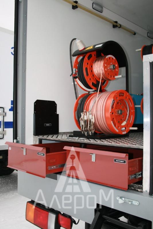
| Cable drums unit | Cable drums unit
External laboratory hook-ups are provided by means of a power cable, ground cable and high-voltage cable. Cable drums VD 4.137.001 – Drum with power cable, cable length is 30 m – Drum with ground cable, cable cross-section is 25 mm2, cable length is 30 m – Drum with high-voltage EPR shielded cable, cable length is 30 m. – Optional. |
|
| Electric safety system | Electric safety check system
The system provides electric safety for laboratory personnel by means of: – monitoring of the chassis potential (trip when the potential exceeds 24V); – monitoring of the earth resistance (trip when the resistance exceeds 25 Ohm); – control of the high-voltage compartment doors (trip with open doors); – manual emergency trip STOP; – automatic forced grounding of high-voltage test units and test units connected to them after completion of tests and in emergency cases; – availability of a visual clearance device supplying voltage; – sound and light signal supply when the laboratory is switched on. Set of instruments and tools: – first aid kit; – dielectric boots; – high-voltage viniplast terminal; – protective orange hardhat; – dielectric mat; – set of driver’s tools; – set of electrician’s tools; – set of warning posters; – carbon dioxide fire extinguisher OU-2 or powder fire extinguisher; – insulating gloves; – high-voltage insulating stand; – high-voltage indicator UVNBU 6-35; – low-voltage indicator; – discharge device; – tie pole SHO-15; – earthing cone. |
|
| Documentation | ||
| Set of documents | – operations manual of the laboratory LVI 3;
– passport for the laboratory LVI 3; – warranty card; – technical documentation for the car; – documents for registration at State Traffic Safety Inspectorate; – metrological certification of the laboratory. |
|
| Warranty and service | ||
| Availability of own service department and production facilities | Arranging a workshop
The main goal of the workshop is to teach users how to operate the laboratory equipment properly. In the process of training, the customer’s specialists learn about the theoretical background of conducting high-voltage tests of power cable lines and methods of finding the damaged spots in them using equipment of LVI HVT, as well as gain practical experience in working with the laboratory equipment. In case of large-scale supplies, the workshop is carried out at the enterprise of the laboratory user. – support service is carried out at the service center in Moscow, Yaroslavl; – warranty – 12 months; – post warranty service for the entire service life; – ability to upgrade the laboratory in operation. |
The high-voltage laboratory performs the following functions:
- – High-voltage tests of power cables up to 35 kV with an alternating voltage of 60 kV of the extremely low frequency of 0.1-0.02 Hz;
- – Burn down of the damaged insulation of power cables;
- – Faultfinding in high-voltage cables using the pulse-echo method and arc reflection method;
- – “Arc reflection method”;
- – Faultfinding in high-voltage cables using the acoustic and inductive method;
- – Selection of a cable from the cable bundle;
- – Faultfinding in the cable sheath;
- – Insulation resistance test;
- – Dielectric loss angle tangent and high-voltage insulation measurement;
- – Determines partial discharge localization on high-voltage equipment items;
- – Measuring parameters of no load operation, short circuit, transformation ratio of power and instrument transformers;
- – Testing switches with the rated current up to 200 A;
- – Testing resistance to the direct current of items having significant inductance.
| №
|
Technical solutions | Operational advantages |
| 1. | Burn-down unit UP-7-05, BD-60 | Automatic support of burn- down and burn-out current.
It can be started automatically from the level of 60 kV. |
| 2. | Generator GVI-32/30 | Pulse energy is up to 3200 J;
Output voltage taps are 8, 16, 32 kV |
| 3. | XDP-2 partial discharge detector
Partial discharge test is a modern method of high-voltage equipment diagnostics |
|
| 3. | Re-equipment of the base car and assembling of the laboratory |
| № | Технические решения | Эксплуатационные преимущества |
| 1 | Прожигающая установка УП-7-05,BD-60 | Автоматический поддержка тока прожига и дожига
Может начинаться автоматически со ступени 60кВ |
| 2 | Генератор ГВИ-32/30 | Энергия в импульсе до 3200 Дж;
Ступени выходного напряжения 8, 16, 32 кВ. |
| 3 | XDP-2 детектор частичных разрядов | Измерение частичных разрядов — современный метод диагностики высоковольтного оборудования. |
| 3 | Переоборудование базового автомобиля и сборка лаборатории | Наш опыт и производственная база ООО «АЛЕРОМ» позволяет делать лаборатории высокого качества, по самым лучшим условиям. |


